
Kick drum mods on a Boss DR-55 Drum Machine
After picking up a Boss DR-55 in beautiful condition, my thoughts turned to gently vandalising it.
There are lots of mods described online in various degrees of detail, so I thought I’d add mine.
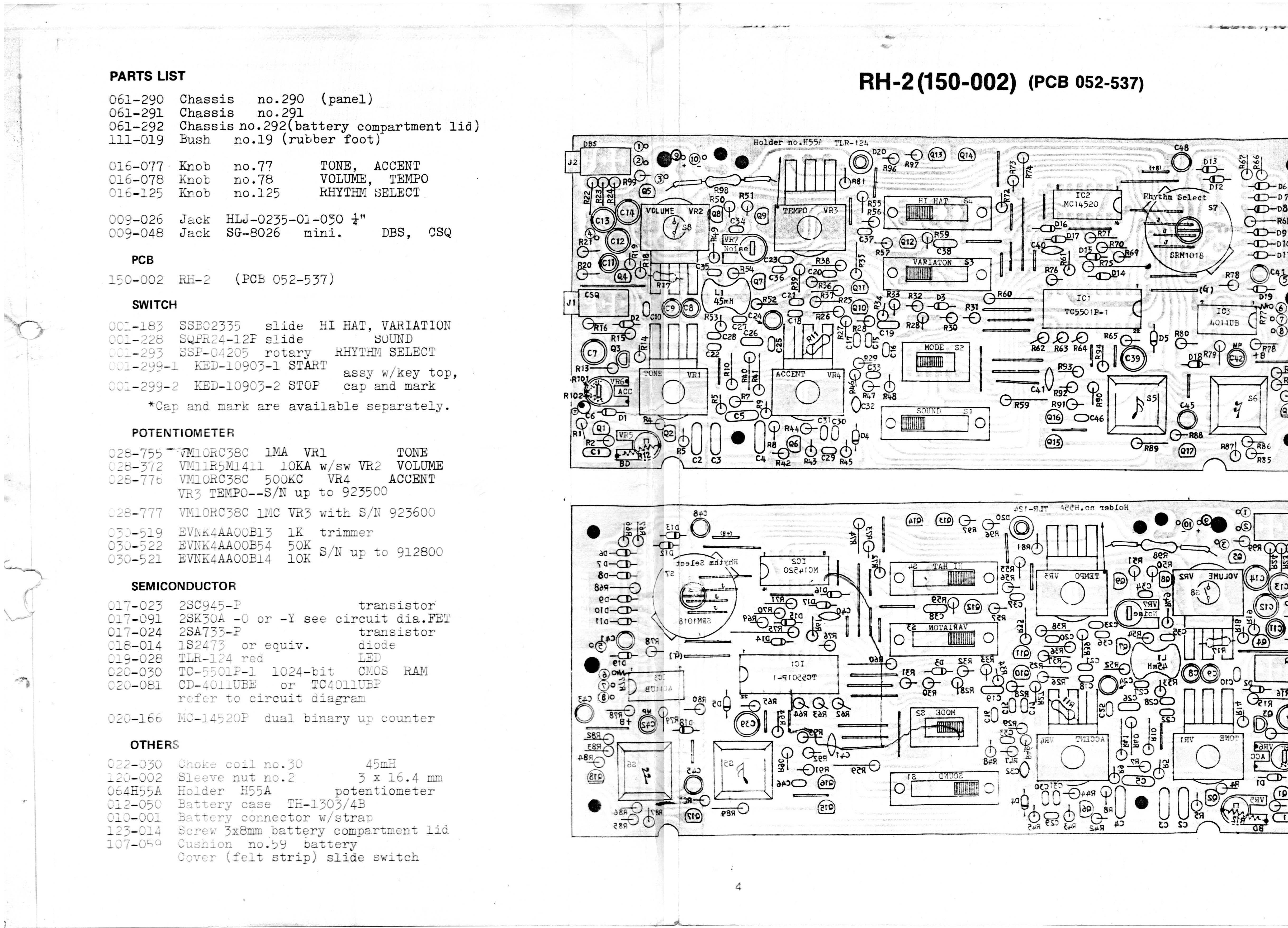
It’s a beautifully made machine, an all-metal case that is very easy to open with eight philips screws. Inside it’s a single-sided PCB (lots of jumper wires) with vertical resistors.
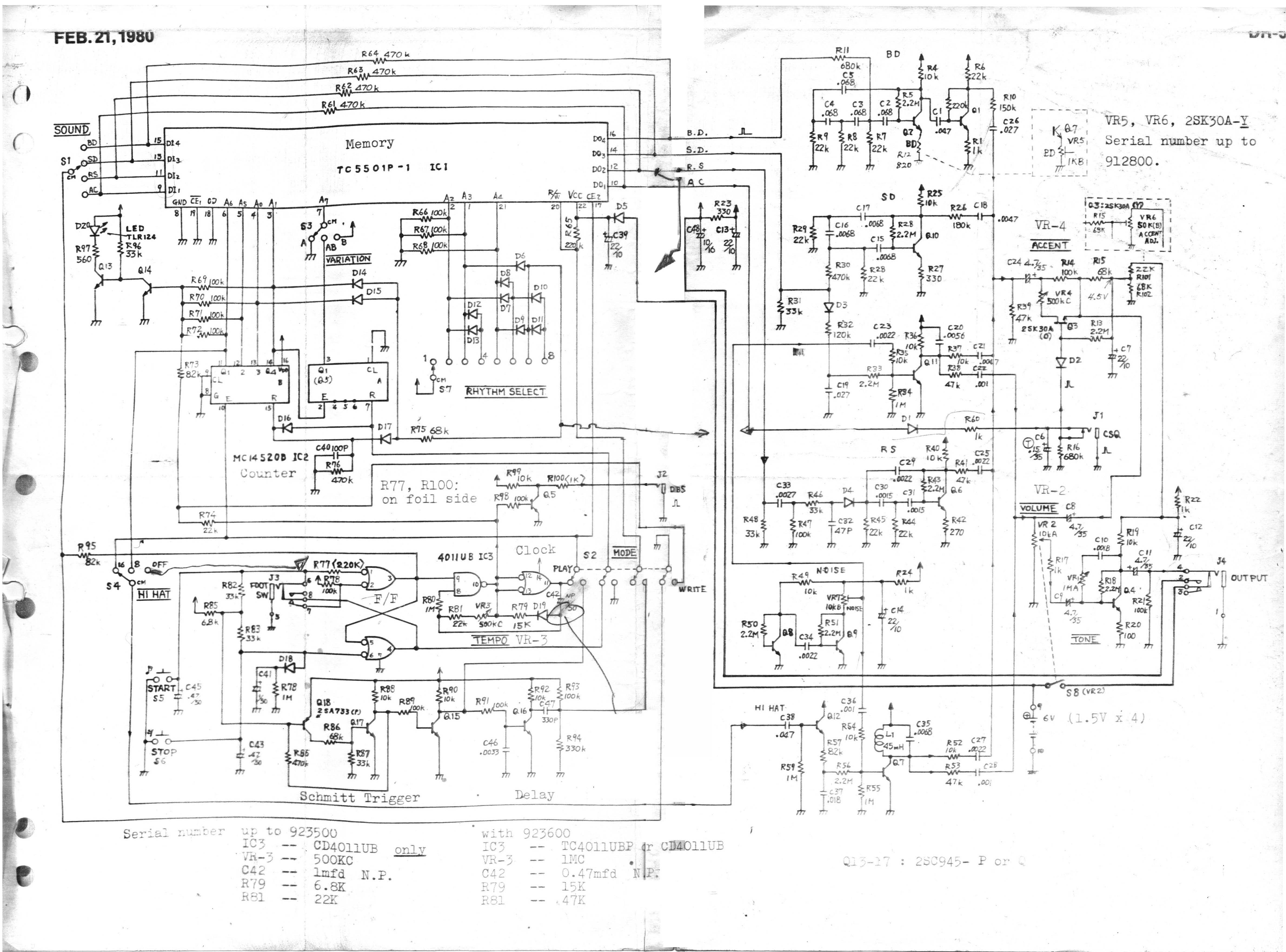
These are based on the schematics from Florian Anwanders‘ site.
Kick Drum Decay
…is very simple: In the bottom left hand corner is a space for a trimmer potentiometer, with a resistor (R12, 820R) soldered across it. Serial numbers below 912800 had the trimmer in place.
R12 is pretty simple to remove. Push the wires up from the bottom with the soldering iron, then lift it off with some tweezers. Mine came out so easily that the PCB holes were still open, but you could clean up with a solder sucker or braid.
Replace the resistor with two wires (two connected strands of ribbon cable work well) going to a 1k Linear Pot.
Connect the wires to pins 1 and 2 (i.e left and middle) on the pot. This gives a super-wide range of decay, from continual loud saturated fuzz to very dry clicking. I also added a 560R resistor between one of the wires and the pot to act as a backstop, but it’s still easy to completely blow the bass out.
Kick Drum Tune v1
…is also simple: Remove R8 (easy to find on the PCB Layout) and replace it with a 100K pot, in the same way as you did with R12.
In use, the two controls really interact. This isn’t like a proper drum machine with a neat pitch/tune control. As you change the Tune control, decay will change dramatically, so you can adjust the other knob to compensate. You can get slightly better results with…
Kick Drum Tune v2
…is a bit more involved, but is still a pretty quick mod.
Here you need a dual-gang 100k linear pot. I happened to have a little 9mm one pulled out of an old stompbox, but otherwise they’re not easy to find that small.
This time, you’re replacing R8 and R9, which as you can see on the schematic, both connect to ground, so you just need three wires. In this diagram you can see which ends of R8 and R9 are in the circuit (red dots) and the end of R8 that is GND (or you could use the other end of R9)
Connect 3 strands of wire to the 3 spots in the diagram. Connect the GND point to Pin 1 on both gangs of the potentiometer, then connect the red spots on R8 and R9 to the Pin 2 (middle) pins on the two gangs.
This gives a slightly better control of kick drum tuning. The control is still sensitive and weird and interacts with the decay control, but it has broader range.
I haven’t drilled my case yet, but it looks like a couple of Alpha 9mm pots will fit nicely on the right hand side below the footswitch socket.