
Radio Music Mk2 Build Guide ←
Radio Music is a 4hp Eurorack module that you can build yourself in an hour or so. The video above shows a complete end-to-end build with full instructions.
- The single PCB is pre-populated with 90 tiny components. Your job is to attach the power header and interface elements: pots, buttons, sockets, LEDs and the SD Card holder.
- It’s not a difficult project, but the density of the board means it probably shouldn’t be the first thing you ever solder. If you also bought a Radio Remote, build that first.
- A few parts of the build are slightly counter-intuitive, so please watch the video or read the text below carefully. If anything is unclear, contact [email protected], send photos.
- NB: This is the build guide for Radio Music kits bought in 2026 and after. For older kits, use this version.
Once you’re finished, use the Radio Music testing guide to check the controls, sockets, LEDs and SD card playback.

What you need to know about soldering before you start ←
- To build Radio Music you’ll need to make about 45 through-hole solder joints.
- Your joints don’t have to be perfect, but for the module to work, they should all look like one of the ‘OK’ joints in the image above.
- Here is a good seven-minute video introduction to soldering from Curious Inventor.
- I recommend Adafruit’s fantastic Guide To Excellent Soldering. The image comes from the common problems page.
Build Guide ←
I recommend watching the real-time build video above, which talks through all stages of building Radio Music mk2 in detail. This guide provides step-by-step guidance.
Tools required: solder, soldering iron, diagonal cutters AKA snips AKA side-cutters, masking tape. A Digital Multimeter is always helpful for checking for bad solder joints and continuity. Thonk sell a range of inexpensive tools.
1. Introducing the PCB ←
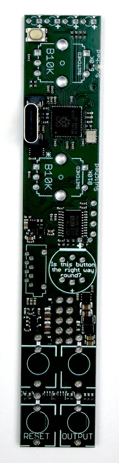
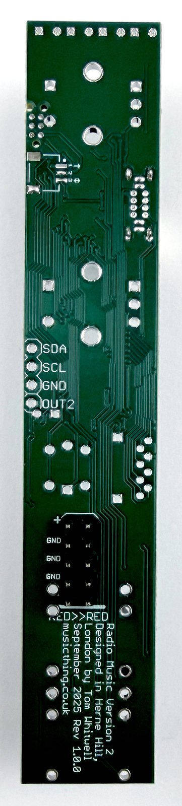
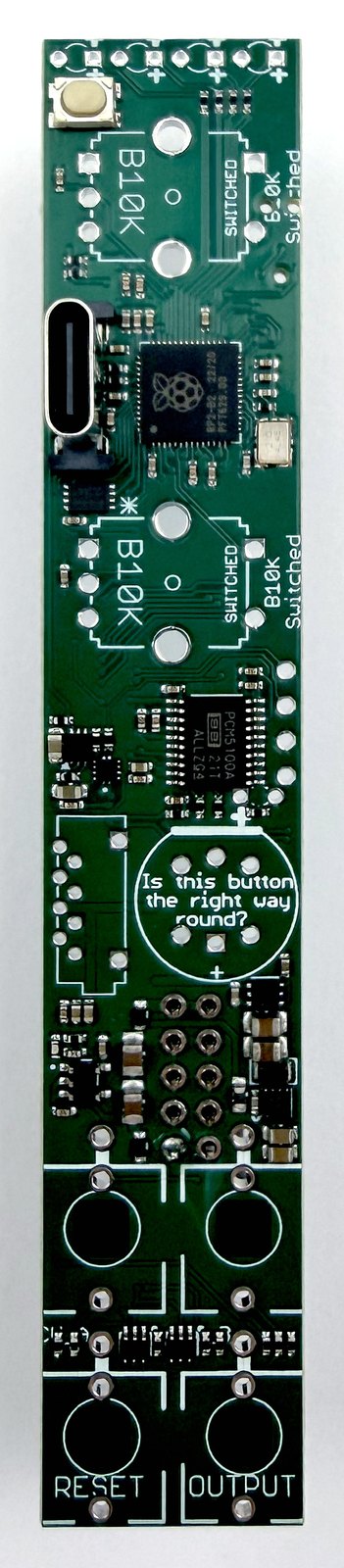
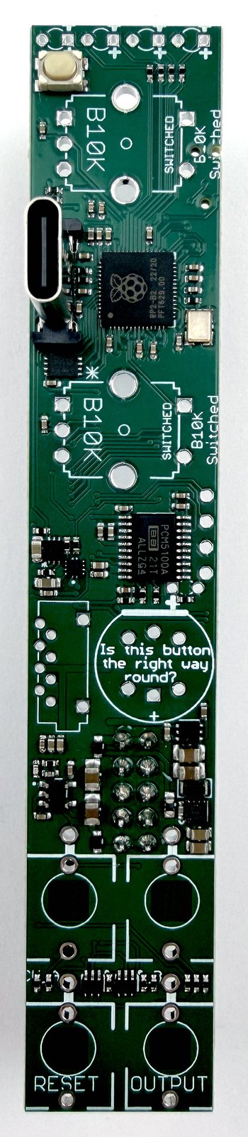
Take a look at the bare PCB.
This is a very dense board with many tiny surface mount (SMD) components already attached. The board has been tested at Thonk, and the microcontroller is already programmed.
The Front side is the side with all the components - including the USB-C socket which pokes through the front panel.
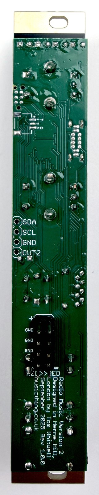
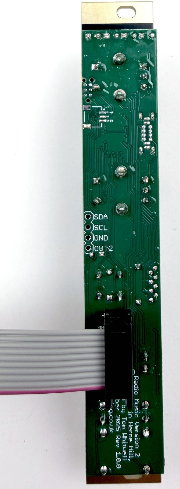
The Back side is the side that faces into the case. It has no populated SMD components but will have the power header connected to the ribbon cable.
2. Attach the power header ←
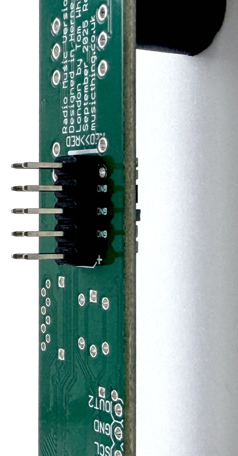
Take great care with this step as it is critical and hard to fix later.
The power header pins are quite large, and the 6 central pins are connected to large ground planes, so require a little bit more heat than usual to solder them. However, if you apply too much heat, the pin can melt the plastic and drop down - requiring a bit of fiddling to get it all aligned.
To hold everything in place I use the four Thonkiconn sockets to lift up the board over the power header and a strip of masking tape to hold the board in place. The video shows my technique for doing this.
Then solder just one pin and check the power header is flush and well aligned. If not, re-heat the pin (make sure you’re not holding that pin with your finger!) and slot it into place.
At this stage, you can also add the optional 4-pin expansion header if it comes with your kit. It won’t do anything until I think of something to do with that header.
3. Fit pots, sockets and LEDs without soldering ←
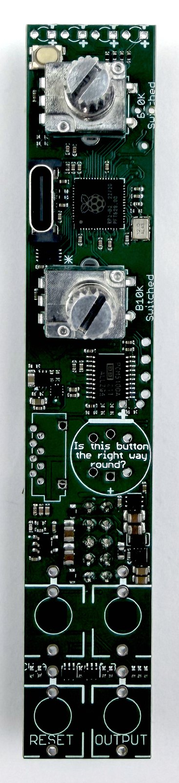
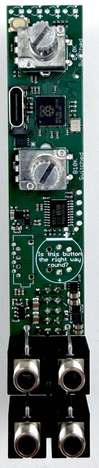
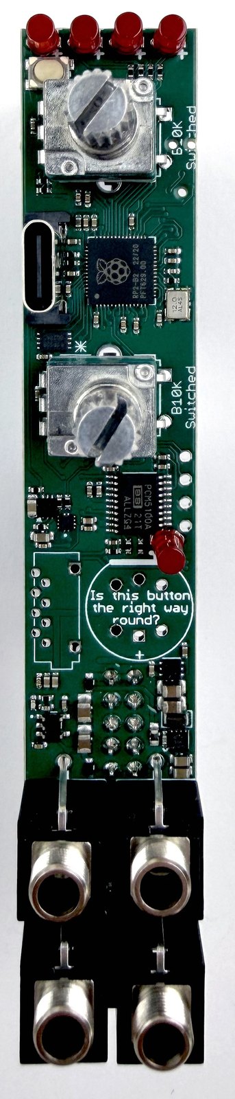
The next step is to put the pots, sockets and LEDs into place, before soldering them.
We’ll come back to do the button and SD Card holder later. If you’re super confident you can do it all in one step.
Pots: These are slightly unusual pots with 5 pins and two legs. They’ll only mount in one direction but make sure all pins are straight and going into the holes
LEDs: LEDs must be oriented correctly. Each LED has one long leg and one short leg. The Long leg goes into the hole marked with a + symbol. There are 5 LEDs, one goes next to the Reset button and is very close to the expansion header.
Sockets: Remove any nuts from the sockets before installing them.
DON’T SOLDER YET.
4. Use the panel as an alignment tool ←
Place the front panel into place. Put a nut onto one of the pots and two of the sockets. Don’t worry about the LEDs yet.
Check the panel and the PCB are parallel and aligned. Give them a squeeze!
Now add some masking tape and push through the LEDs to keep them aligned to the panel. If you prefer, you can also push them straight through - it’s purely aesthetic.
DON’T SOLDER YET


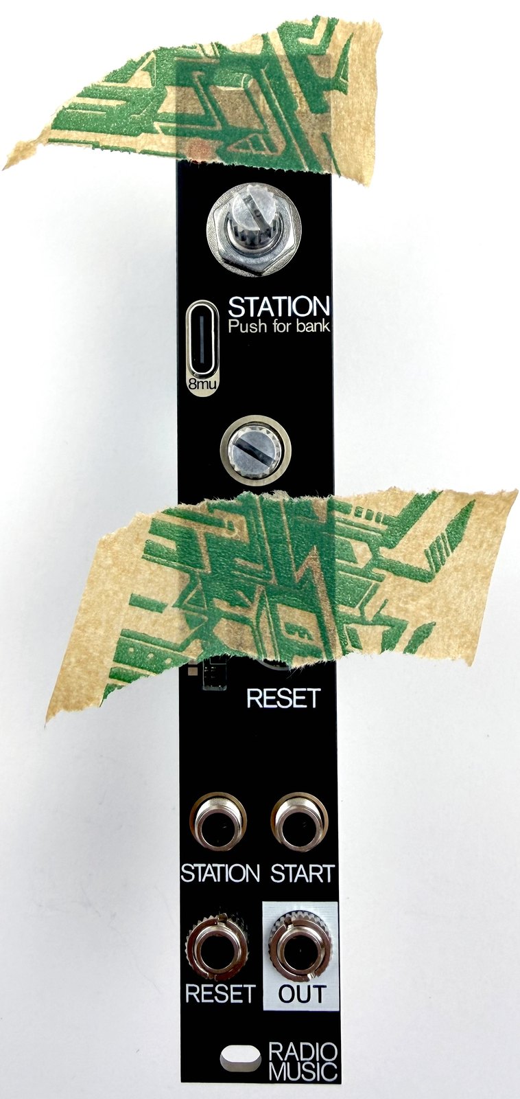
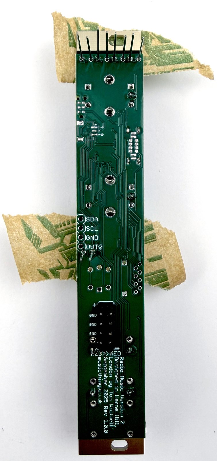
5. Check everything, then solder ←
Check again that the two boards are parallel, that all the LEDs are the same height. Check the long LED legs are through the pins marked +.
SOLDER!
Once you’re happy, solder one pin on each component - one LED leg, one pin on a pot (not the big legs), one pin on each socket.
I recommend this because it’s easy to reposition or fix a part when only one pin is soldered. If it’s out of place or not flush against the PCB, you can just reheat that joint and snap it into place.
Check again. Once you’re happy everything is aligned, go back to solder all the points.
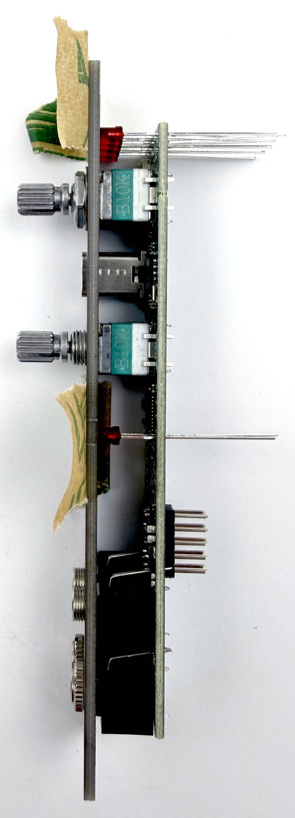
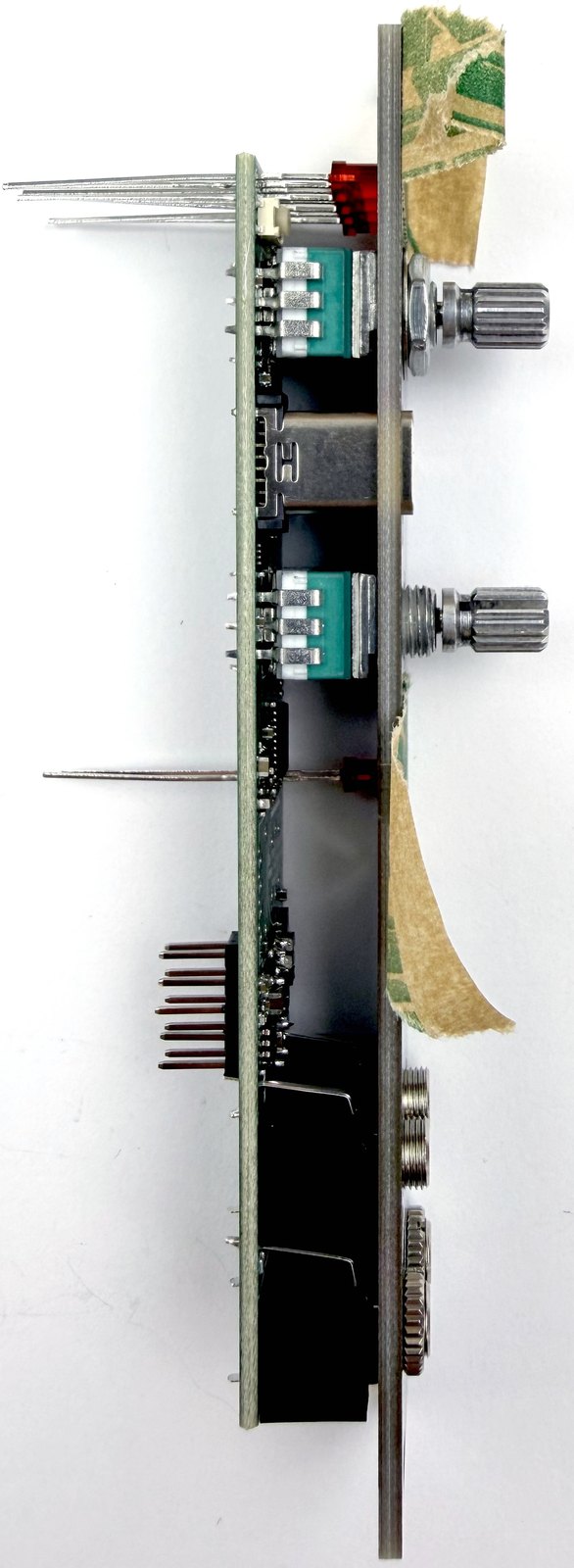
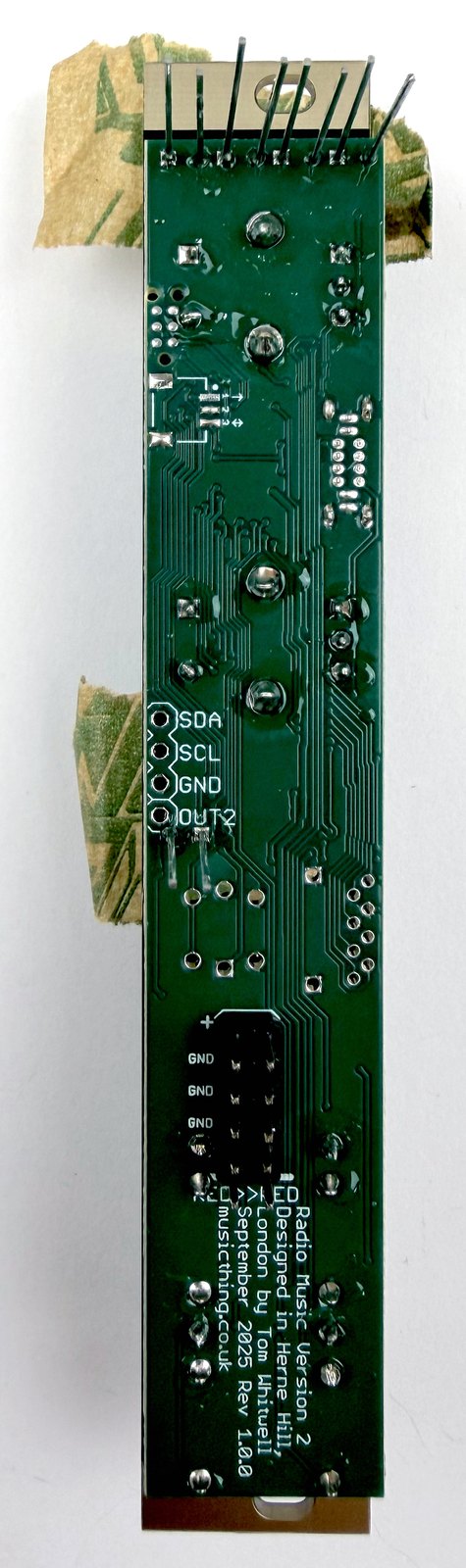
6. Add the button and SD card holder ←
Now go back and add the button and SD Card holder. These are the fiddliest parts to mount, so take it slow and steady.
The pushbutton has one flat side. Make sure this side matches the flat side on the PCB artwork. There are two very fine LED pins under the pushbutton, make sure they’re not bent and can go through the holes.
The SD Card has very fine pins. Check none are bent then place it on the board.
Attach the front panel and tape the SD Card Holder and pushbutton into place.
At this stage, the ‘solder one pin first’ rule is particularly important. Solder one of the larger pins on the pushbutton, and one of the larger ‘leg’ pins at each end of the SD Card holder.
Gently remove the tape and check…
The SD Card holder should be flush against the PCB at the bottom, and aligned with the slot in the panel.
The pushbutton should also be flush against the PCB, and it should work smoothly when you tap it, not rubbing against the panel.
Once you’re happy, solder all the pins. The tiny pins on the SD Card holder are very tiny, but the soldermask makes it easier than it looks to solder them cleanly.
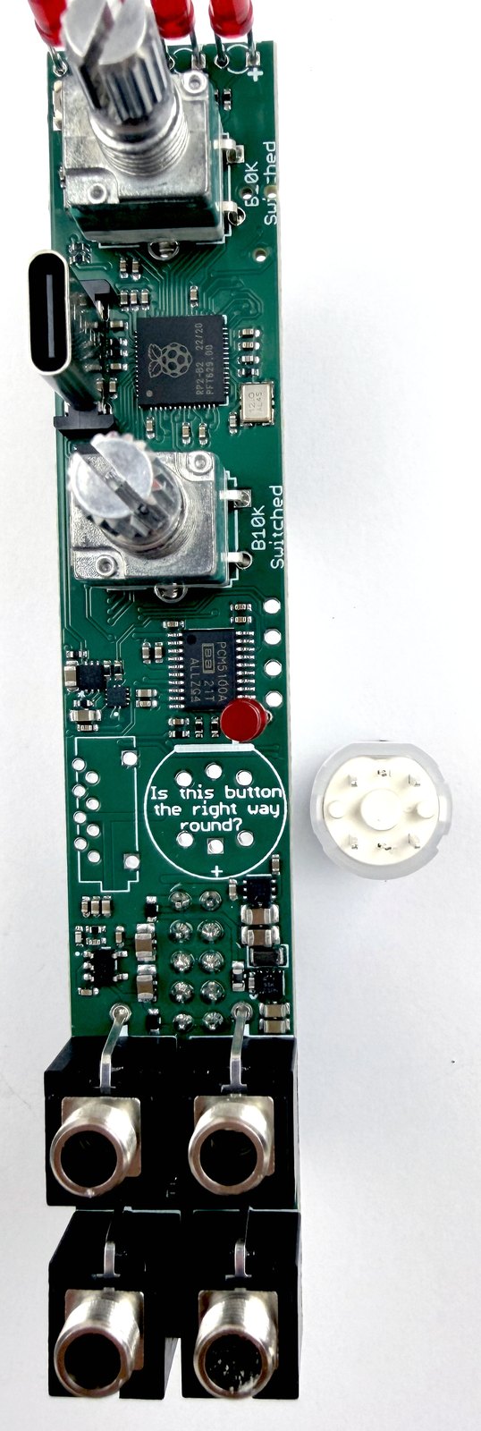


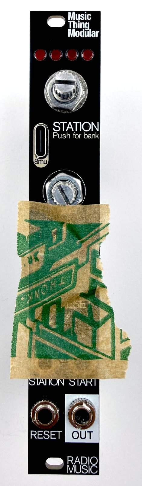
7. Checking, trimming and finishing ←
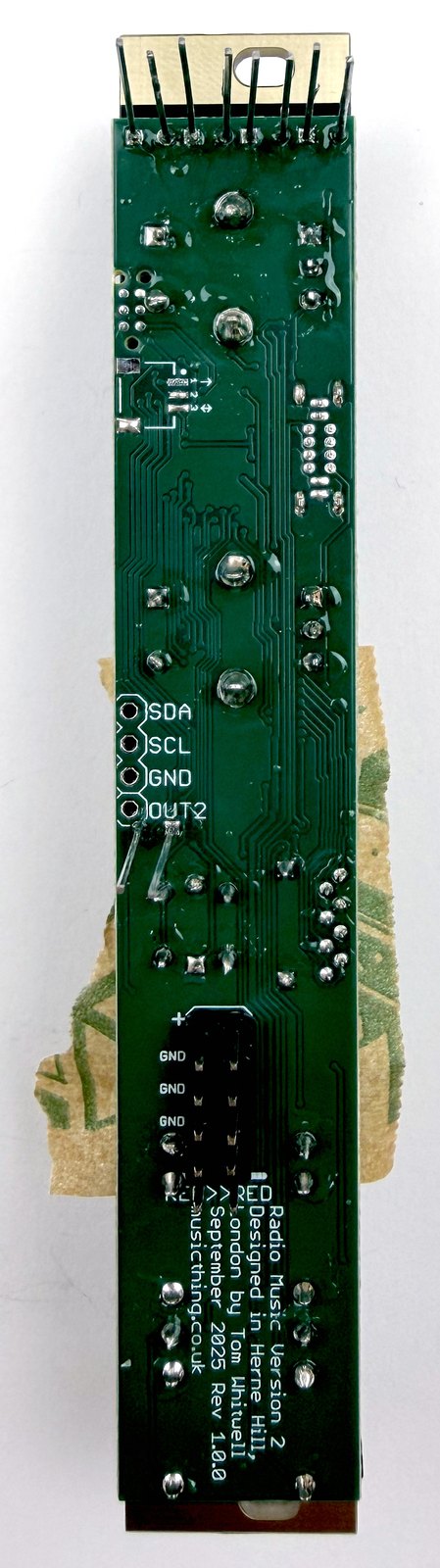
Now check your work. If you have one, get a magnifying glass and some bright light to check each of the solder joints on the back. You’re looking for missed joints (I always miss at least one joint, somehow), and blobby joints that don’t look like the OK joints in the picture at the top.
Add any missing joints, reflow any you’re not sure about. You don’t need perfection, just ‘OK’ joints. It’s not normally about adding more solder, although sometimes that is required.
At this point, trim the long legs of the LEDs. This can also reveal a missing joint, or a point to touch up.
Once you’re happy, you can finish the build:
Add the rest of the nuts and tighten them using pliers with tape wrapped round the end, or a fancy tool if you have one.
Push on the knobs. These push straight on. Make sure the knob buttons still click when they’re on.
Add the power cable. You’re done.

Testing ←
Once you’re finished, use the Radio Music testing guide to check the controls, sockets, LEDs and SD card playback.