
8mu v2 Manual and Support
Documentation
Build Guide ←
8mu v2 is a very small MIDI controller that you can build yourself in an hour or two.
- The PCB is pre-populated with 70 surface-mount components.
- Your job is to solder the eight through-hole faders, then put the front and back panels together with quite a few small screws.
- It’s a good first DIY project. not much soldering but a quick satisfying build.

What you need to know about soldering before you start ←
- To build 8mu v2 you’ll solder eight through-hole faders. The 70 small surface-mount parts are already installed.
- Your joints don’t have to be perfect, but for the controller to work, they should all look like one of the ‘OK’ joints in the image above.
- Here is a good seven-minute video introduction to soldering from Curious Inventor.
- I recommend Adafruit’s fantastic Guide To Excellent Soldering. The image comes from the common problems page.
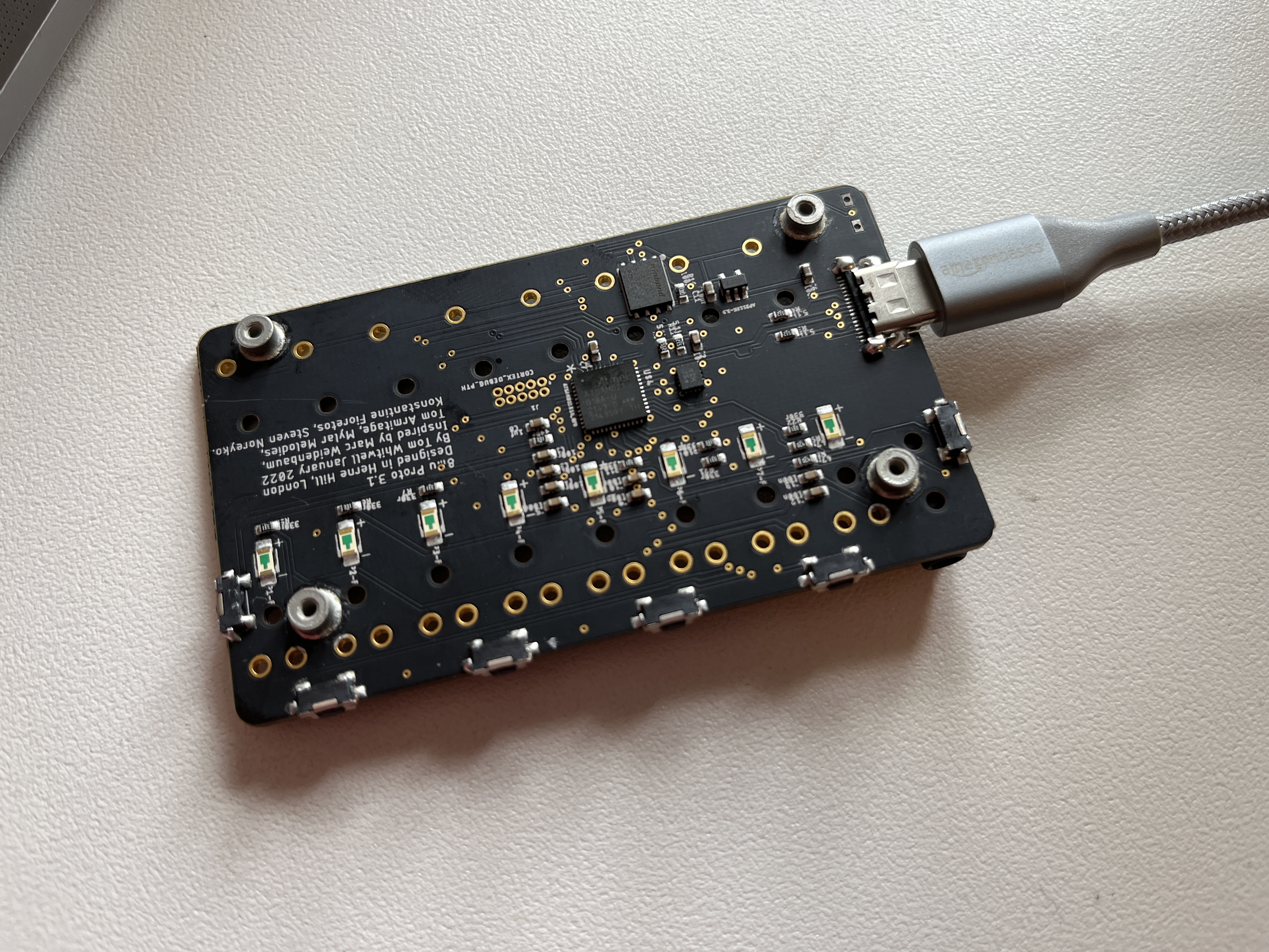
1. What am I looking at? ←
- The pictures on this guide show 8mu v1 boards. Your v2 board will look very slightly different, and not have the very tiny gold circles that were a manufacturing error on these old prototypes.
- All 8mu v2 boards have been individually tested at Thonk, and the most recent firmware has been pre-loaded.
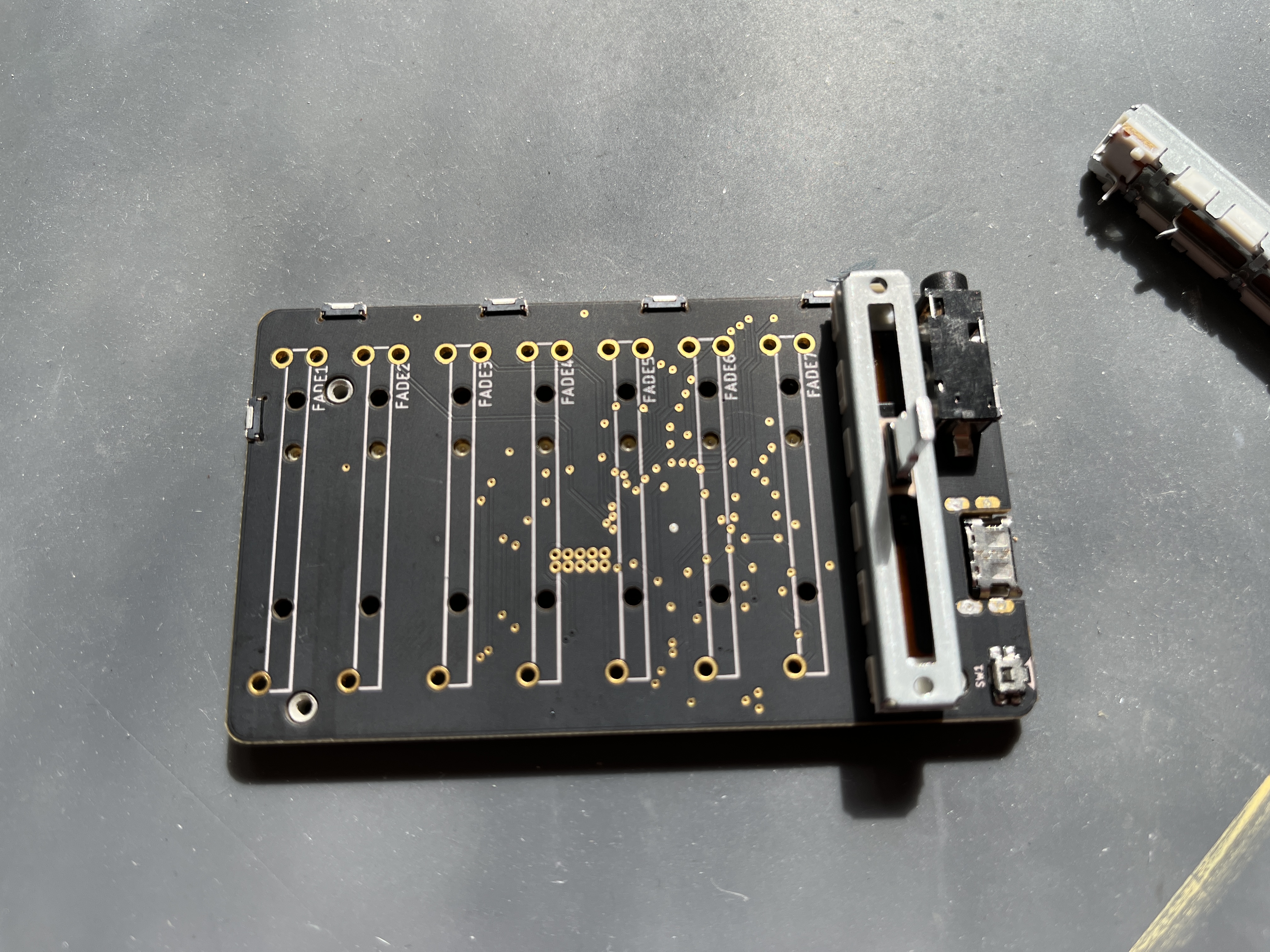
2. Start putting it together ←
- Assembly is pretty straightforward: Soldering on 8 faders, then screwing on the front and back panels
- Take it slow, ensure everything is mechanically lined up before you solder anything in place.
- IMPORTANT: The faders go on the top of the board, next to the 3.5mm MIDI socket. Most of the small components and chips are on the bottom of the board.
- Don’t solder anything yet.
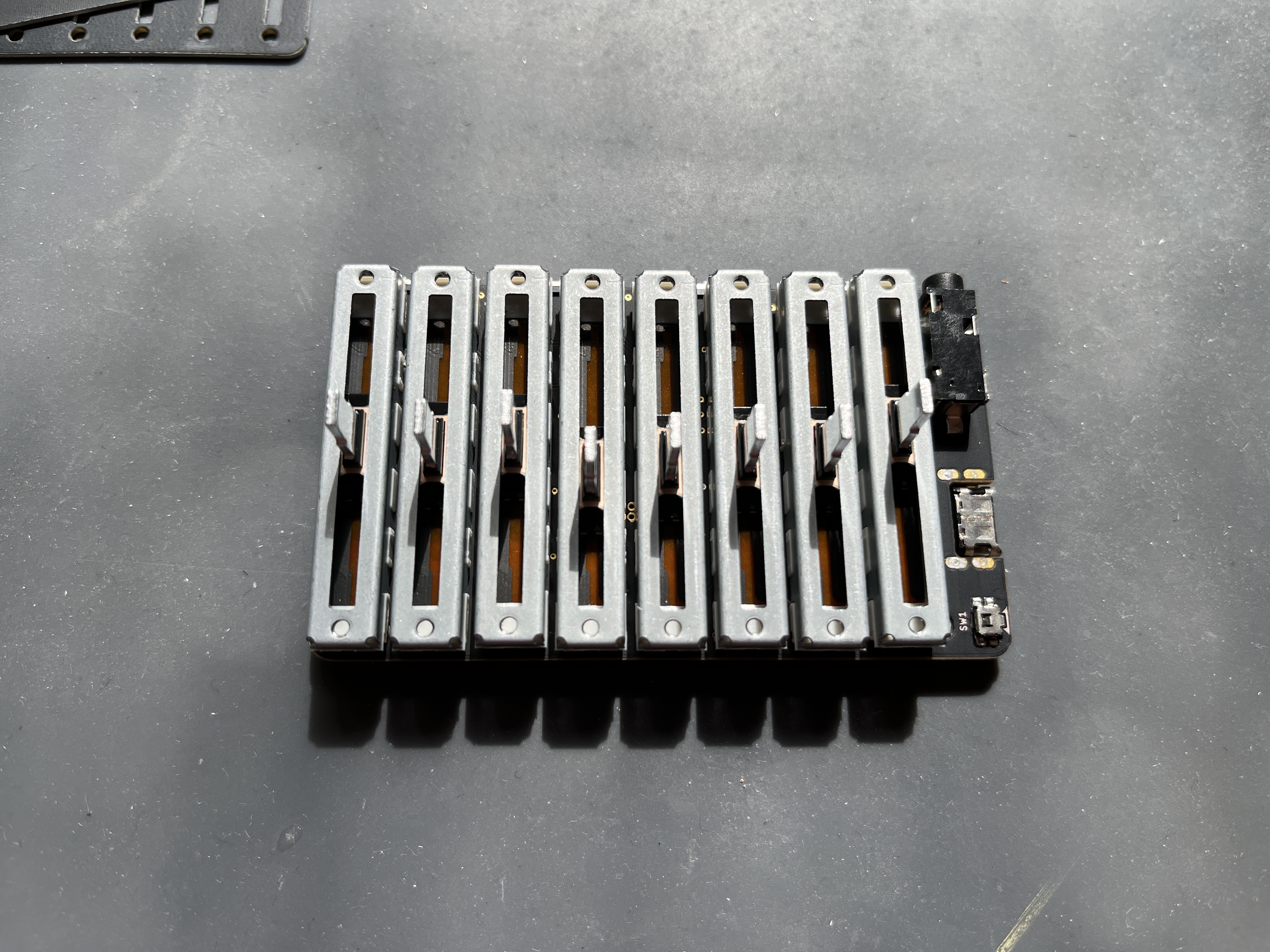
3. Place the faders ←
- Start by putting all 8 faders in place on the board.
- The faders have 2 pins on one end, 1 pin on the other end. They align with holes on the board.
- Check that the pins on the faders are all straight before you put them into place.
- There are also two metal clips on each fader that go through holes on the PCB. These should clip into place with a satisfying clunk. Watch the video at the top if you’re not sure.
- Don’t solder anything yet!
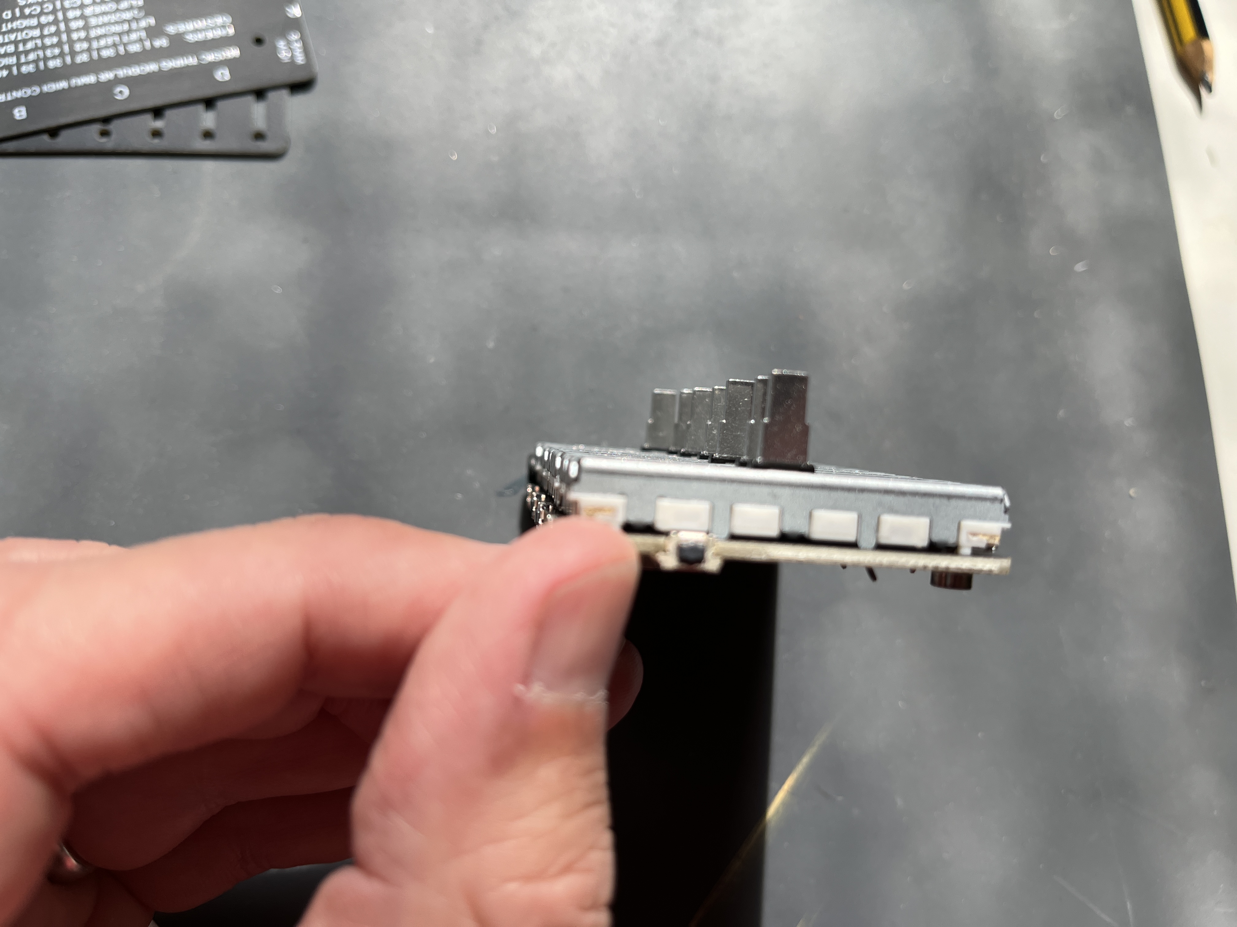
4. Check fader alignment ←
- Before soldering: Ensure the faders are flat and aligned with the board.
- Don’t solder anything yet!
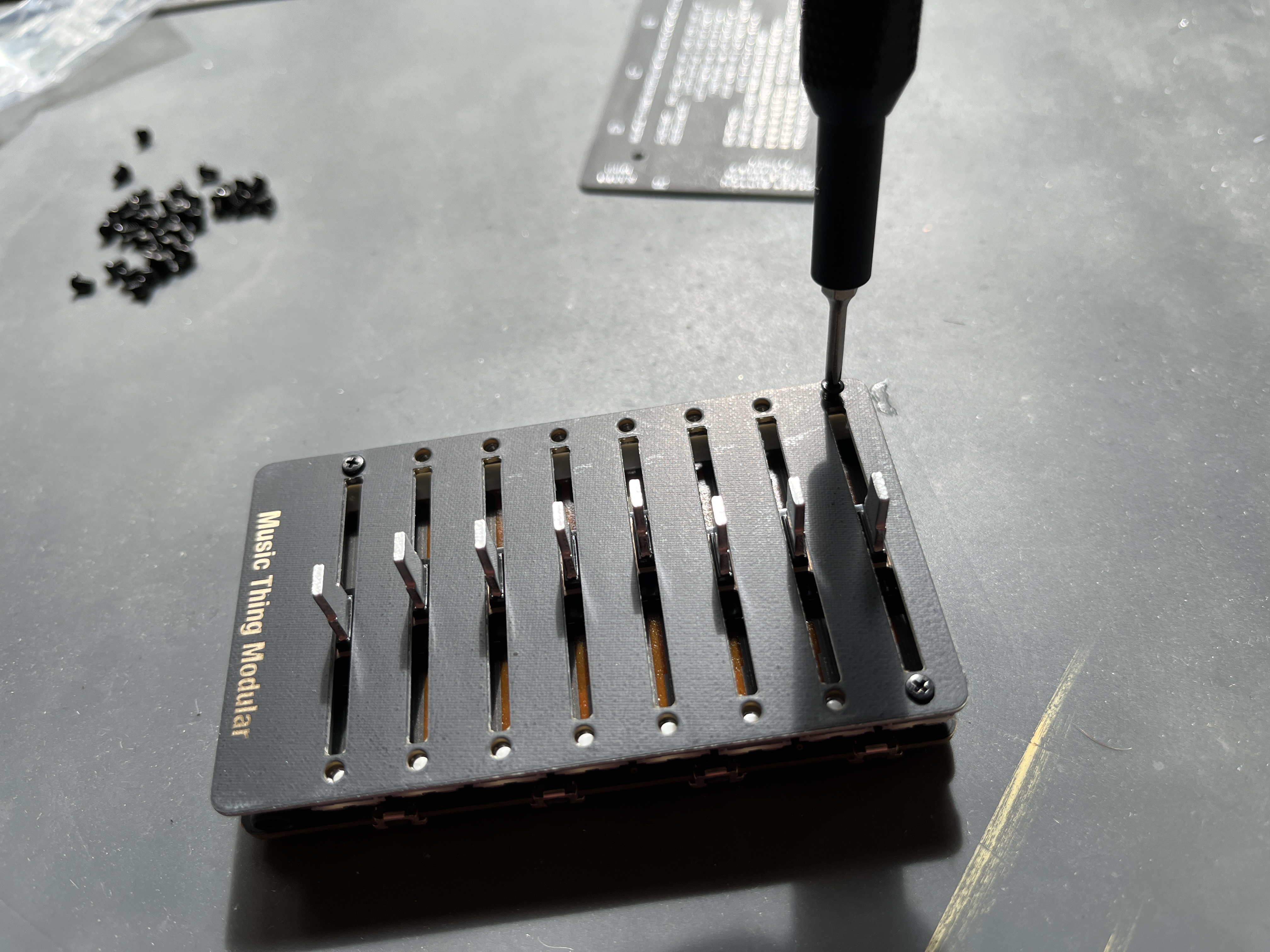
5. Screw on the front panel ←
- Put the front panel in place, and add the 16 x m2 screws.
- The perfect size is a 2.5mm philips screwdriver but 3.0mm works well. 2.0mm is the standard ‘glasses’ size screwdriver and that works ok, but can damage the screws if you try and go too tight with it.
- Don’t solder anything yet!
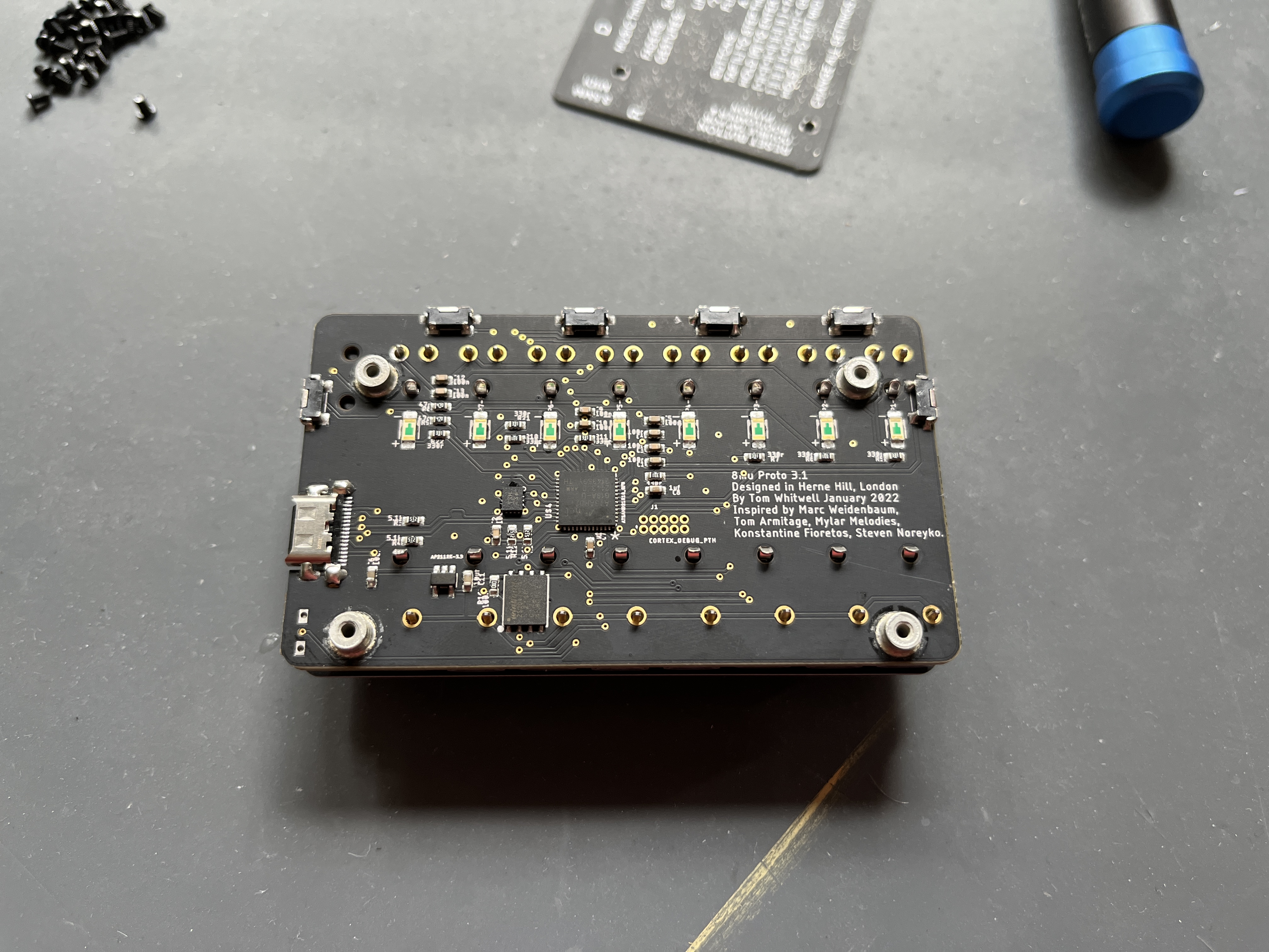
6. Now it's time to solder ←
- Check all the pins are going through the holes, that none are folded underneath.
- Do solder the pins at both the ends of the faders that go through gold holes
- Don’t try to solder the clips on the faders that go through black unplated holes - there’s nothing to solder onto.
- The pins on the faders are quite large, so need some time to absorb the heat - go slowly and ensure the solder is flowing down into the holes
- Be careful not to touch any of the tiny surface mount components with your soldering iron
- Check your work carefully - it’s surprisingly easy to miss a connection, and annoying to debug later - you can get weird random errors
- Watch the video at the top of this page if you’re unsure.
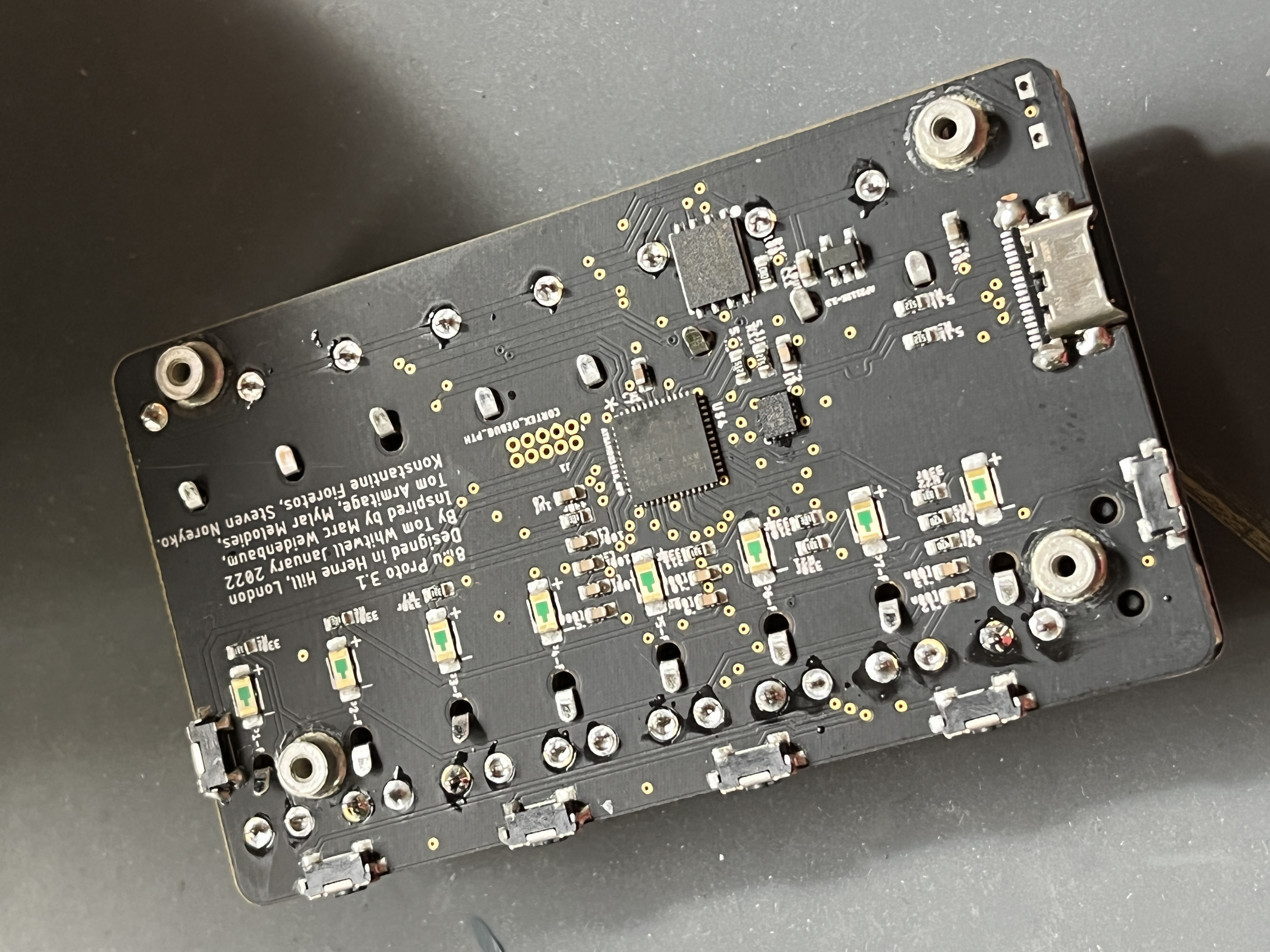
7. Fold down the fader clips ←
- There is just 3mm clearance between the PCB and the back panel
- But the fader clips and the fader legs may be longer than 3mm
- So, gently fold the ends of the fader clips down onto the board - use a little screwdriver. There are little ‘shadows’ on the PCB artwork to show you were they should go.
- Watch the video at the top of this page if you’re unsure.
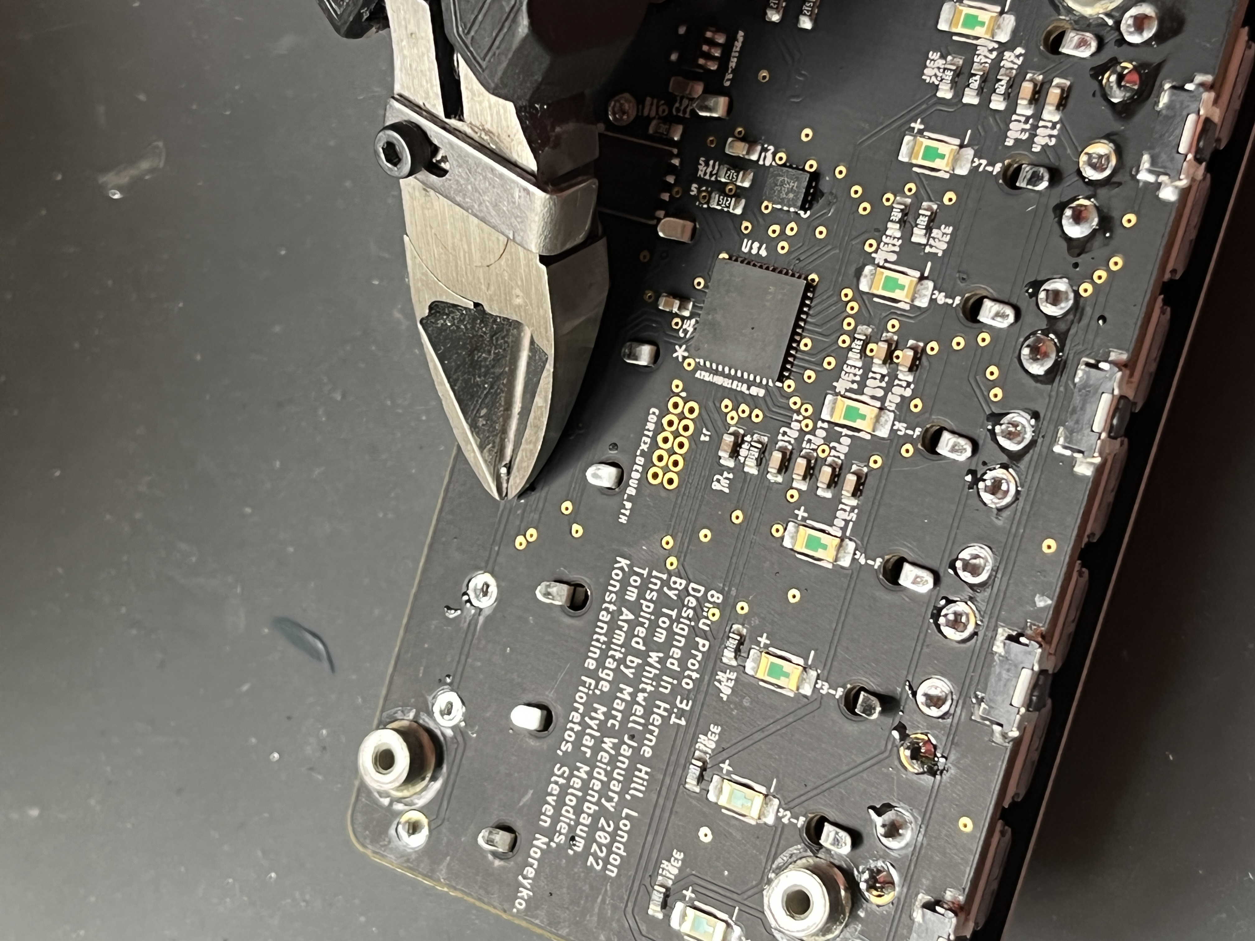
8. Trim the fader legs ←
- Carefully trim the legs of the faders with some diagonal trimmers.
- Be careful not to mash up any of the little SMD components.
9. Finish it off ←
- Screw on the back panel with four m2 screws
- DON’T WORRY if you have a couple of spare screws left - Thonk put in extras in case you drop one.
- Attach the rubber fader caps. Lightly squeeze the rubber caps between your fingers for 20-30 seconds. This warms them up and makes them more malleable to get on the faders.
- The 8mu was designed to be hand-held, but here are a few ideas about mounting your 8mu.
- Use stick-on rubber feet if you’re putting it on something that might scratch
- Non-slip silicone gel pads work well for safe semi permanent mounting on keyboards, desks or walls.
- Velcro tape works for stompbox-style mounting
- That’s it, make yourself a cup of tea to celebrate.
User Manual ←
In Use ←
- It’s pretty simple.
- You plug the 8mu into your computer.
- 8mu will show up on your computer as “8mu2040”.
- 8mu sends out MIDI data over USB. Your DAW (or a browser, or pD or whatever) can pick up that MIDI data.
- If you want to change how the data is used, you make changes in your DAW - you’ll have to read the manual for that. For example, in Ableton Live, you need to go to Settings / MIDI / MIDI Ports and check ‘Remote’ next to Music Thing M0 Plus.
- If you want to change how the data is sent, you make changes in the 16n/16nx/8mu editor where you can configure which controls are sent on which CC and channel.
The Editor ←
- The Editor lets you configure your 8mu in a browser, and monitor the outputs from faders and accelerometer channels in real time.
- The browser (Chrome) talks to the 8mu via old-fashioned sysex messages, so it takes a second or two to connect, and to update when you change banks.
- Having trouble? In late 2026 Chrome had a MIDI bug that is now fixed.
Banks ←
- The device stores 8 independent banks of settings
- By default, all banks are identical
- Tap the left or right buttons to move up and down through the banks
- You’ll see the bank LED move
- After a second, that bank will be selected and you’ll see an LED confirmation animation
- The editor configures the current bank - it has no visibility of the other banks.
- The current bank remains between power cycles. If you move to bank 4, then never change bank, the device will always be in bank 4.
- To move or copy a bank, use the editor to “Export current config” of that bank. This downloads a little local file. Then switch banks, and import that configuration.
MIDI Learn mode ←
- The accelerometer channels send a lot of data as the device moves. This makes it really annoying to use MIDI learn, for example creating custom MIDI mappings on Ableton.
- It’s hard to map a control to Fader 1 when the accelerometer is spitting out lots of movement data.
- So, 8mu has two MIDI Learn modes which temporarily turn off accelerometer outputs.
- In the first, the accelerometer channels are simply turned off, so data from the faders is clean.
- In the second, the faders are mapped to accelerometer channels, so they can be predictably controlled. So, to map filter cutoff to ‘Lift Front’, enter MIDI Learn Mode 2, and move the first fader. Exit MIDI Learn mode filter cutoff will be correctly mapped.
- Getting in and out of MIDI Learn mode:
- Hold the RIGHT button.
- LEDS will flash 🟡🟡🟡🟡⚫⚫⚫⚫
- You are in Fader mode, accelerometer gestures are disabled
- Hold the RIGHT button again:
- LEDS will flash ⚫⚫⚫⚫🟡🟡🟡🟡
- You are in Gesture mode, the accelerometer gestures are mapped to the 8 faders
- Hold the RIGHT button a third to EXIT MIDI learn mode.
- Should this be Teach Mode, or Learn Mode? I’m not sure.
Updating the firmware ←
- Firmware update instructions to come. Right now, there is only one version of the firmware which is installed at Thonk.
A note on battery power ←
- 8mu draws a maximum of about ~30mA of power
- This isn’t enough to keep many USB Battery Packs active - they shut off after a few minutes, sometimes in weird ways.
- So, you need a battery pack with an ‘Always on’ or ‘Trickle Charging’ mode: Voltaic Systems are slightly expensive ‘pro’ batteries designed for timelapse photography, but Anker batteries are normally priced and have a trickle mode that lasts 2hrs before needing to be restarted.
Backing up 8mu settings ←
- Use the ‘Export current config’ button in the editor to download the current bank as a json file.
- Then, click ‘Edit config’ to import a local json file.
- Unfortunately you have to do this for each bank separately.
Troubleshooting ←
- Many people have built and used 8mu successfully, but here are a few things to try if you’re having problems
- No MIDI in my DAW: If the 8mu faders move in the editor, that shows that MIDI signals are being generated by the 8mu, and received by your computer. If they’re not appearing in your DAW or other software, it’s probably a config issue in that software, rather than 8mu.
- MIDI Learn is confused by random midi signals: If you’re using Midi Learn to pair your DAW or synth with 8mu, there are two possible sources of random MIDI.
- The accelerometer channels will send midi whenever you move the device. If you’re not using them, you can turn them off (turn the channels to 0) in the editor. Or you can use MIDI Learn Mode to temporarily turn off the accelerometer channels.
- When using the editor, the board may send midi ‘refresh’ signals and lots of Sysex every so often, so don’t use the editor while setting up MIDI learn.
- Dead faders: Dead faders - where a fader output is stuck on high, or low, or in the middle - can caused by soldering problems. To troubleshoot a dead channel…
- Then reset the 8mu settings by holding down ABCD at startup
- Then check the 8mu isn’t in MIDI learn mode - with 4 of the LEDs flashing.
- Then you can be confident it might be hardware, so remove the USB cable, take off the back panel and carefully check your soldering
- Re-read the instructions and ensure the pins on the ends of each fader are properly soldered. The pins are quite large, so you might need to hold your soldering iron to them for 5 seconds to properly melt the solder and have it flow into the hole.
- Ensure you’ve trimmed the board and folded down the clips.
- Test the board again with the editor. If you still have problems and you’re a Thonk Customer, contact Thonk support to ask for help.
- Dead buttons If you have a dead button, it’s likely to be a hardware issue, so contact Thonk support to ask for help.
Hacker's Guide ←
8mu v2 is powered by an RP2040 so is relatively easy to hack and modify. I will be sharing more information in future.
Getting help ←
- The first place to check for help is this page. It contains pretty much everything I know about 8mu.
- The second place to check is the 8mu Issue List here on Github. Remember to check for closed issues.
- The third way to get help is to walk away - sleep on the problem, write a note to yourself explaining the problem and what you’ve tried. This often helps you find a solution.
- The fourth place to check is the person who sold you your 8mu, particularly if you bought an assembled 8mu from someone.
- Finally, Thonk customers can contact Thonk support to ask for help if you get stuck. If you think it might be a hardware issue, include high resolution photographs of both sides of the PCB.